README
Open on GitHub ↗Resurrected random guitar pedal project
This is a resurrected version of my old guitar pedal project: a digital
guitar pedal built around an RP2354A and a TI audio codec, with all the
effects done in software on a core of its own.
It went through a phase with a little OLED screen and a couple of rotary
encoders on it, and that's gone now. Editing seventeen effects through a
128x128 screen and two knobs was never going to be pleasant, and I'm not
exactly known for my mad UI designing skillz, so the pedal itself is down
to one knob and one stomp switch and the deep editing happens somewhere
that already has a screen: there's a web app that talks to it over USB
MIDI from a browser.
So what's in here:
Hardwarehas the kicad files.Effectshas the seventeen effects, one file each. They are up here
rather than inside the firmware because three different things are
built from them: the firmware, the test bench, and the web app's
controls.Audiohas the DSP the effects are built out of - biquads, envelope
followers, LFOs - and the audio loop itself. The bench compiles the
same files, so what gets measured is the pedal's own arithmetic.Firmwareis the rest of what runs on the pedal: USB, MIDI, scenes,
the board pin maps.WebMIDIis the web app that edits it.scriptsis what the build runs - the effect generator, the math
tables, and the checks that refuse a firmware image doing something
the audio core shouldn't.Validationis the test suite. Some of it runs on your machine and
some of it wants a pedal plugged in.Documentationremains a very optimistic name for a directory.
Firmware
I've only ever built the firmware on Linux, but it should be perfectly
possible to build on MacOS or Windows too if you just figure out the
platform requirements. The project depends on the pico-sdk andtinyusb libraries and on picotool, and has submodules for all three, so
they get built automatically, but the build tools your platform has to provide.
Regardless of platform, you'll need the basics:
- git
- make
- python3
- cmake
- a C and C++ compiler for the machine you build on, because picotool
and the SDK's PIO assembler are built from source too - pkg-config and the libusb-1.0 development files, for picotool
(libusb1-develon Fedora,libusb-1.0-0-devon Debian)
and a 32-bit arm cross-build environment. On Linux, that would be
something like
- arm-none-eabi-binutils-cs
- arm-none-eabi-gcc-cs
- arm-none-eabi-gcc-cs-c++ (the SDK sets up C++ as well as C)
- arm-none-eabi-newlib
On Fedora that whole list is
dnf install git make python3 cmake gcc-c++ pkgconf-pkg-config \
    libusb1-devel arm-none-eabi-gcc-cs arm-none-eabi-gcc-cs-c++ \
    arm-none-eabi-newlib
The ble board also carries the nRF54 radio's firmware, which is a
Zephyr build of its own. make -C nRF54 fetch sets that up once: a
python venv with west in it, the Nordic SDK, and Zephyr's ARM toolchain
in ~/zephyr-sdk-*, about 7.5GB between them. It also needs ninja
(ninja-build on Fedora).
There's more than one board this can be built for, and the build won't
guess. You say which one this tree is about once, inboard.local, and it stays said - it's a file rather than a
cmake cache variable specifically so that blowing away build/ doesn't
silently change your mind for you. So:
	git clone https://github.com/torvalds/GuitarPedal.git
	cd GuitarPedal
	echo unified > board.local
	make prep
	make
unified is the current one-board pedal. The other is split, which is
the older modular pair of boards. If you forget this step the configure
will stop and tell you, which is the intended behaviour - a wrong board
should be an error you fix once, not a working build for hardware you
don't have.
That gets you build/pedal-unified.uf2 (and .elf, and .bin). Every
artifact is named for the board it's for, so there is deliberately nopedal.uf2 to grab by mistake. You can build the other board without
changing what the tree is about - make split - or both with make all-boards.
To get the .uf2 onto the pedal you need it in BOOTSEL mode, and there
are two ways. If it's running and plugged in, send it MIDI CC 20 with
value 126 and it will reboot into BOOTSEL on its own:
	amidi -l                          # find which card the pedal is
	amidi -p hw:5,0 -S "B0 14 7E"     # ...and that 5 is mine, not yours
Otherwise, hold the knob in while you plug it in. The rotary encoder's
switch doubles as BOOTSEL on this board - through a Schottky, so that
QSPI traffic can't fake pulling it low - and that's the route that still
works on a pedal too broken to enumerate. The older boards had a proper
BOOTSEL button, but it was on the little MCU daughtercard, which is fine
on a bench and useless the moment the thing is screwed into a box.
Either way a USB mass storage device shows up and you copy the file to
it.
The build makes its own picotool, with USB support, so you can also skip
all that and just do make flash, which builds and flashes the board inboard.local.make flash-split does the other one.
Tools outside the tree
Two tools stay outside the tree, and each has a make target that
sets it up once per machine. Both say what they are missing, and
running either again is safe.
make probe-rs builds probe-rs, which programs and debugs the nRF54
radio through the pedal, from ~/src/probe-rs into ~/bin/probe-rs.
It needs cargo and the libudev development files (systemd-devel on
Fedora).
make build123d makes a python venv in ~/.build123d for the
3D-printed case in Hardware/Models, and two commands in ~/bin that
use it: build123d Compact.py runs the model, and ocp-viewer is
the viewer it draws in, at http://localhost:3939.
Talking to the pedal without root
picotool and probe-rs open the pedal's USB device directly, and without
a udev rule only root can. This is /etc/udev/rules.d/99-pedal.rules:
ATTR{idVendor}=="2e8a", MODE="0660", GROUP="dialout"
ATTR{idVendor}=="ffff", ATTR{idProduct}=="0003", MODE="0660", GROUP="dialout"
The first line covers anything with Raspberry Pi's vendor id, which is
how a board in BOOTSEL shows up; the second is the running pedal, whose
CMSIS-DAP interface is what probe-rs uses for the radio. You have to be
in the dialout group, and udevadm control --reload as root plus a
replug picks the rule up. USB audio and MIDI need no rule.
The pedal's debug console is /dev/ttyACM0, which needs a kernel withCONFIG_USB_ACM. Every distribution kernel has it; a kernel you
configured yourself may not.
Testing
Validation has the test suite, and it's split by what it needs.
make check needs gcc and numpy (python3-numpy), plus node if
you want the web app's tests too; without node those are skipped. The
bench scripts that talk to a pedal want more: alsa-utils, ffmpeg, scipy
and matplotlib, ngspice for the circuit comparisons, and dbus-python and
PyGObject for Bluetooth MIDI. On Fedora,
dnf install python3-numpy nodejs alsa-utils ffmpeg-free psmisc \
    python3-scipy python3-matplotlib ngspice python3-dbus python3-gobject
make check runs the part that needs no hardware at all: the MIDI
packetiser, whether the web app still loads and still draws the right
conclusions, and a sweep that asks every biquad in the pedal where it
actually landed. make check-biquad is that last one on its own, andmake check-effects puts signals through the effects themselves.
That last one works because of Validation/bench, which builds the
pedal's actual audio core - the same single_sample(), the same effect
headers, the same compiler flags - as a program on your machine that
takes float samples on stdin and hands them back on stdout. It is not a
model of the signal path. It's the signal path, with the two register
blocks the audio core touches replaced by ordinary memory.
make check-analysis is the other host-only one, and it is what keeps
the per-effect pages under Documentation/effects honest: every curve on
those pages is a measurement, and this re-measures and says when one has
stopped being true. It is separate from check because it re-runs
every sweep on every page, which is slow.
Then there are the ones that want hardware: make check-hw with a
signal generator, make check-analog with a patch cable from the
pedal's output back to its own input, make check-bench to ask whether
a real board agrees with the host build, make check-hwtone to sweep
the tone stack the codec runs in its own biquads, and make check-loop
if you have two pedals to patch into each other.
Hardware
The kicad design files (and some supporting infrastructure, like the 3D
printed insert and the enclosure drill rules) are in the Hardware
subdirectory.
These days it's just the one board. Hardware/usb-stomp has the RP2354A
and the TI TAC5242 codec sitting directly on it, and that's the whole
pedal: no cable, no daughtercards, no connectors in between.
What's on it:
- a 1/4" input jack and a 1/4" output jack
- a third 1/4" jack for an expression pedal or a remote stomp switch
- MIDI in and out, on 3.5mm "Type A" TRS jacks (out through a 5V
buffer, in through an optocoupler, like MIDI has always wanted) - USB-C, and the usual 9V guitar pedal power jack
- one rotary encoder with a switch under it, and one stomp switch
- three addressable WS2812B LEDs
The MIDI jacks and the expression jack are the genuinely new things. The
older boards had nowhere to put them - the expression jack in particular
wants two ADC pins, and those are exactly the pins the old MCU board was
spending on hardware MIDI, so it could not have existed there at all.
Fair warning on that expression jack, though: the hardware is done and
the firmware can read it, but only when the host asks it to over SysEx.
Right now it's a probe for figuring out what people actually plug in
there - expression pedals don't even agree on which contact is the wiper
- and nothing is wired up to do anything with the result yet.
How it used to be
It used to be modular, and those board files are all still here. There
were two little daughtercards for the "core" hardware - the RP2354
microcontroller (Hardware/rp2354) and the TI TAC5112 codec
(Hardware/codec) - plus a board for the audio and 9V DC power jacks
(Hardware/audio-jacks), and a main board (Hardware/pedal-board) for
the pedal IO: i2c connector for the screen, USB-C programming port,
rotary encoders, pin header for stomp switches. The two halves were
joined by a 12P 0.5mm FFC cable carrying power and data lines (i2c for
control, i2s for audio).
That was mostly so I could try out different form factors. It let me lay
the two halves out independently, and it was flexible enough to cram a
125B enclosure full of jacks, rotaries and the screen all in one top
area. There was also a worry about noise isolation, which in the end
never had to be tested.
I used the nice HiRose BM28 series connectors on the modular boards.
They are absolutely tiny, which makes for a great board footprint but
admittedly also makes for a slightly more complicated board due to the
tiny 0.35mm pitch. I'm not a fan of the traditional pin headers simply
because they make it so hard to do compact form factors.
Those boards are finished and they still work - the firmware builds for
them, and they're still useful for testing. But what this section used
to say was that if you know what you want, you should just put the codec
directly on the audio jack board and the rp2354 on the IO board. Which,
yes. That's the board above.
Images
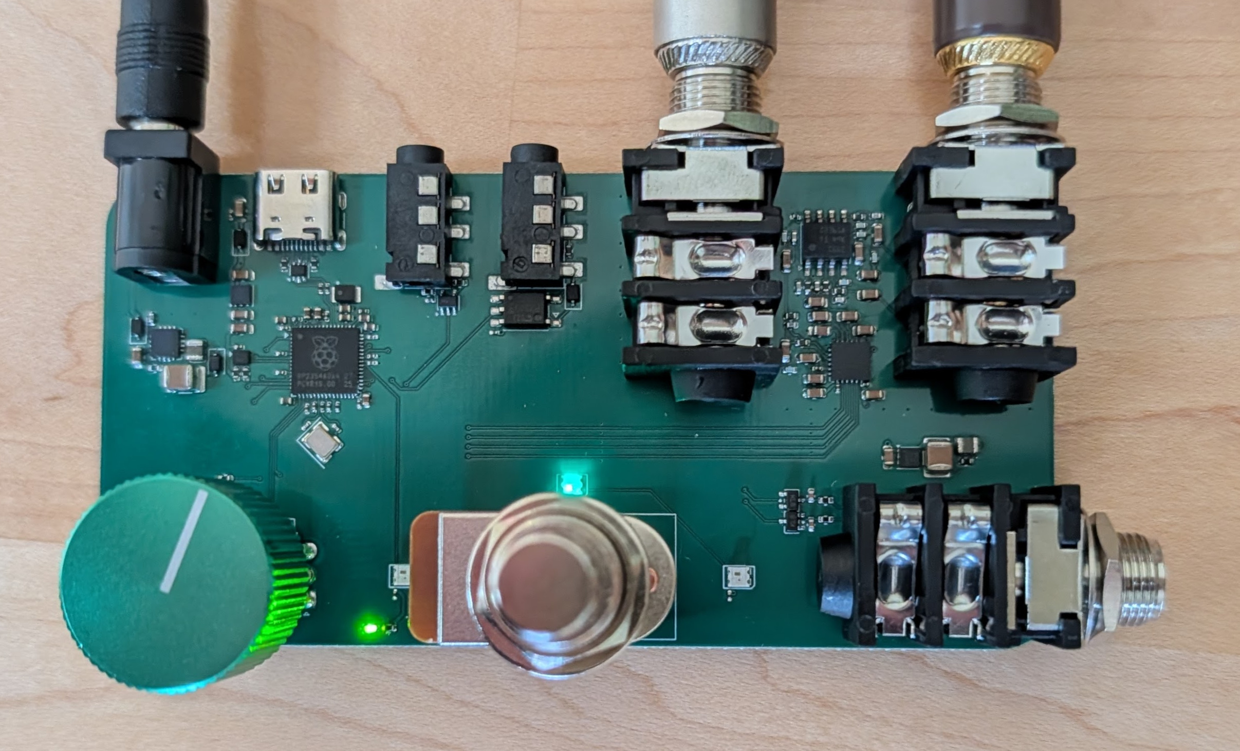
The bare usb-stomp board, powered up.
Basic UI
There's no screen. The pedal has one knob, one footswitch and three
LEDs, and everything else happens in a browser.
On the pedal
Out of the box the footswitch is bypass - tap for in-circuit or not, hold
it for the tuner - and the knob is the master volume, with either kind of
press on it putting the volume back where it started. That last one
sounds trivial and isn't: it's the way back when you can't see anything.
But none of that is compiled in. There are five gestures - turn the
knob, tap it, hold it, tap the switch, hold the switch - and what each
one means is a table the pedal looks up and the app writes. You can
point the knob at any parameter of any effect, or make a single press
take one effect's mix up while it takes another's down. A pedal with no
screen can't tell you what its knob is for, so that has to be settable
from something that can.
The three LEDs, left to right: something is wrong (red for clipping,
amber for dropped samples), in circuit or bypassed, and the chain is
busy - where "busy" means whatever the effect thinks it means, so the
gate lights it while it's gating and the compressor while it's
compressing.
In the browser
WebMIDI is a static web page that talks to the pedal over USB
MIDI. There's nothing to install and it runs off a phone.
It also talks to the pedal over Bluetooth MIDI. On Linux, Chrome only
offers Bluetooth to a page withchrome://flags/#enable-experimental-web-platform-features turned on;
USB needs nothing.
It doesn't know what the effects are. It asks. The pedal describes
every effect it has - every pot, the ranges, the units, the hover text -
and the app builds itself out of that, so it can't drift out of step with
the firmware, and adding an effect to the pedal makes it show up in the
app without touching the app.
What you actually do there is route. There are seventeen effects and
none of them are in your signal path until you say so: routing picks
which ones run, and in what order, and the order is yours, because a
boost in front of a delay is a different pedal from a delay in front of a
boost. Whatever you don't route costs nothing.
Pots are mostly just numbers, except where they aren't - the tone stacks,
the parametric EQ and the cab sim draw their actual frequency response,
so you can see the curve instead of inferring it from three knob
positions.
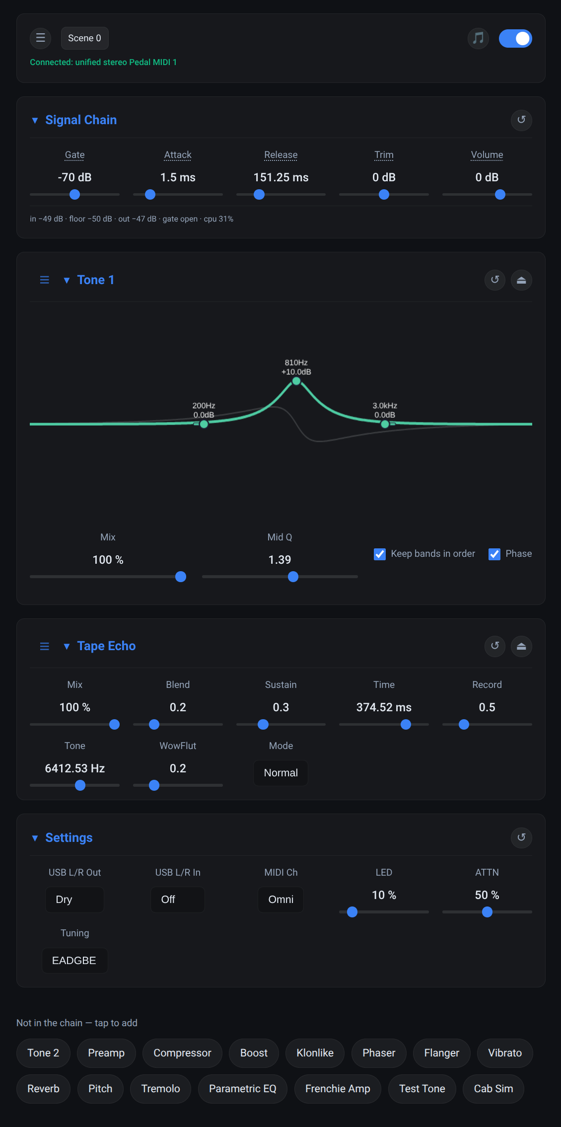
A tone stack with a 10dB mid bump at 810Hz and a tape echo behind it, and
the fifteen effects that aren't routed sitting at the bottom waiting to
be. The faint grey line is the phase response.
Eight scenes fit in the pedal's own flash. A scene is a routing plus
everything set inside it, and a MIDI program change recalls one, which is
half of what those MIDI jacks are for: a cheap footswitch can step
between scenes with no computer in sight.
Audio effects
Nineteen of them, plus five that are always there and can't be
unrouted: the Signal Chain at the front, which is the input trim, the
noise gate and the master volume
(measured), and behind them the
Settings, which is whether the input jack is carrying one channel or
two, the MIDI channel, LED brightness and what the tuner is tuning to,
the USB Audio, which is what crosses the wire in each direction, the
Bluetooth Audio, which is where audio from a phone joins, how loud it
is and what goes back, on a board with a radio, and the Expression Jack, which is what
is plugged into it and where that thing's travel ends.
They're listed in the order they run in by default. This is an overview
and not documentation - the app is the reference, because it gets the
ranges, the units and the hover text from the pedal itself rather than
from anything I typed here.
- Hum Filter - removes the hum single coils and noisy power put on
the guitar, cutting only the hum's own frequencies, so a clean supply
gets no cuts at all. Switching it on the first time, or moving the
target, listens for a few seconds with the sound left on, so you hear
the hum go: keep the strings quiet while it does. It runs ahead of
the noise gate. It does not reach the high buzz some USB chargers
add, and a power bank is quieter there anyway. - Tone - bass, mid and treble, with the corner frequencies
adjustable and the mid's Q as well. There are two of them, so one
can go in front of a distortion and one behind it. - Analog In Tone and Analog Out Tone - the same three bands
again, running in the codec's own biquads rather than in the chain.
They cost the audio core nothing, and they keep the two channels
apart where Tone folds them together. Routed like anything
else, but drawn at the ends of the chain because that is where they
are: analog is the operative word, and they sit outside everything
USB audio can reach, so a Dry capture has already been through the
input one and a Wet capture has not yet been through the output one.
They need a board whose codec answers on i2c. - Preamp - a two-stage 12AX7 model, class-A biased with the
asymmetry left in, and a JFET stage after it. - Compressor - level, ratio, attack, release, and a boost, so it
can also just be a clean boost when that's what you want. The
threshold reaches low enough to work on a quiet pickup with nothing
in front of it. Measured. - Auto-Wah - an envelope filter that sweeps a resonant filter with
the guitar's pick dynamics, by Jacky Mpoka. Lowpass mode preserves low-end body while
sweeping harmonics (Mu-Tron III style); Bandpass mode isolates the
resonant peak for classic vocal wah (Crybaby style). Sweeps up for
funk quack or down for synth sweeps. - Boost, with distortion. I like this one. Others may not. Set
the boost stupidly high and the level low, and instead of clipping at
the level the signal folds back down, which gives you harmonics
that a soft or hard clipper doesn't. - Klonlike - the obvious model: 18V charge pump for headroom,
germanium diodes, and the clean/dirty blend that tracks the gain
knob. Originally by Bryan Leavelle.
Measured. - Rat Sketch - a ProCo RAT, from the Aion FX Helios clone. One
op-amp with up to 67dB and several decibels an octave of treble
emphasis inside the feedback, then diodes to ground, then the one
backwards Filter knob. Three clipping modes, because the pedal has
three. The op-amp saturates inside its own loop and the diodes are
solved rather than approximated, which is where its second harmonic
comes from. Measured. - Phaser, Flanger and Vibrato - the modulation three. All
simple, all a delay line and an LFO wearing different hats. - Tape Echo - the Echo King from Cleveland Music Co, a model of the
Maestro Echoplex tape delays, converted from the Hothouse examples.
All credit to Ricky Sheaves, and blame me for the conversion. - Reverb - comb filters into allpasses, the traditional way.
Measured. - Pitch - not the clever FFT kind. It walks a delay line faster or
slower than real time in two phases, crossfaded with a sine so the
wrap doesn't click. So it shifts and delays, and it feeds back into
itself, which makes it a short echo that shifts again on every repeat.
Most natural an octave up, but it does fractions. - Tremolo - amplitude modulation, several shapes.
- Parametric EQ - five bands, two shelves and three peaks, every one
of them tunable across the whole range. - Frenchie Amp - a small amp: triode, tone stack, power amp.
- Test Tone - sine, triangle, saw or noise at a known level and
frequency. It replaces the input rather than adding to it, which is
what lets the pedal measure itself. - Cabinet - a speaker cone as a moving mass rather than as a filter,
integrated at the sample rate. Pick one of five cabinets and it knows
the rest of itself; the knobs are how hard the amp drives it, how much
the amp lets its resonance bloom, and where the mic is pointed.